SEAN'S RC EXTRAVAGANZA
Construction
...
The construction process so far has included the use of 3D printing, CNC mills, and manual mills. The 3D-printed parts needed the holes to be drilled out to the proper diameter. The part made using the manual mill needed a custom fixture made in order to machine the corner fillets. The CNC machine was the easiest way to make parts for the RC car, making the program for the parts took about twice as long as setting up material in the mill, but the CNC was able to machine parts faster and the surface finish was more desirable, and the programming process should speed up with practice. The CNC was used to make the majority of the machined parts for the drivetrain and chassis as the parts produced were more consistent with dimensions and tolerances. The chassis took the longest to manufacture as the mounting holes in the mounting plate took 3 tries before they were the correct size and lined up with the holes in the chassis and various human errors done by the project engineer led to a few setbacks and involved making a new "blank" of carbon fiber before the chassis was completed to the specified dimensions.

Fig. 5 Transmission mount maching
This image is of the Transmission mount after the two corners were filleted. In the background is the fixture that was made in order to use the rotary table on the Bridgeport to make the fillets.
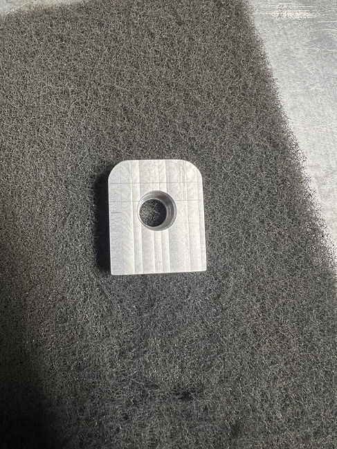
Fig.6 Transmission Mount Cleaning
This picture shows the Transmission Mount during the cleaning process after the machining was completed.

Fig.7 Surface Finish From Manual Mill
This image shows the surface finish that was achieved using the Bridgeport mill. The stock in the picture was used to machine the Motor mount.

Fig.8 Motor Mount CNC
This image is of the motor mount after the first two operations were completed using the CNC mill. The first operation was milling out the shape of the part and the second operation was milling out the slot for the driveshaft. The remaining operations include the holes to mount the motor to the mount and the holes to mount the mount to the chassis.

Construction Video 1
This video shows part of the machining of the motor mount (fig. 8). As shown in the video the aluminum was machined using coolant to keep the part cool and to preventy warping and to help clear chips out of the way.
Fig. 9: Completed Chassis (Left) and Mounting Plate (Right).
This picture shows the chassis (left) after it was finished being machined on the Bridgeport Partenr mill. The picture also shows the mounting plate (right) and the multiple attempts at drilling the mounting holes in the plate.